Grain boundaries simulation
Note
Before reading this tutorial, please refer to Simple simulation of a substrate tutorial as the following only gives supplemental information concerning grain boundaries geometry.
A grain boundaries geometry is similar to a multi-layers with the exception that the layers are vertical instead of horizontal. In other words, the interfaces between the layers are perpendicular to the surface of the sample.
Unless the sample is rotated, the layers in a grain boundaries geometry are along the y-axis (the normal vector of the interface points towards the x-axis).

Schematic of a grain boundaries geometry.
If a line scan is performed over the grain boundaries geometry (see Create a batch of simulations), the x position of the beam must be changed.
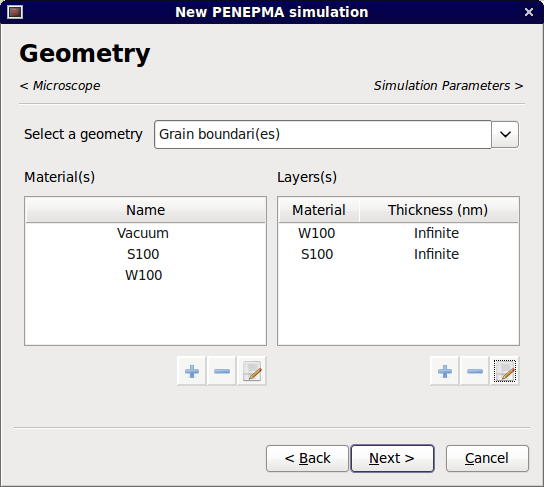
The setup of a grain boundaries geometry is similar to the one for a multi-layers. Materials and layers are added in the same way. However, two substrates must be specified on the left and right hand side of the layers. It should also be noted that, in opposition to multi-layers, a grain boundaries geometry does not require the user to define at least one layer. In other words, the geometry can be made out of 2 substrates to create a couple.

Geometry and materials panel with a grain boundaries geometry selected.
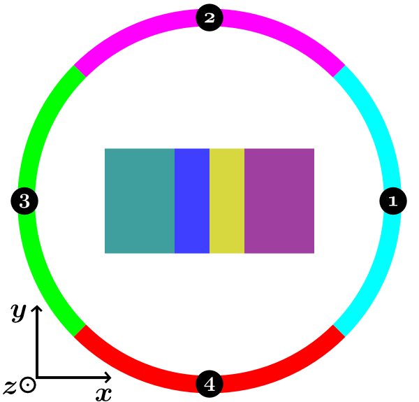
The default photon detectors are adapted to take into consideration the heterogeneity of this geometry. Four sets are automatically defined for a total of 40 detectors. Each set spans an azimuthal angle of 90 degrees. The following schematic illustrates the position of the detectors with respect to the sample’s axes.

Position of the photon detectors.